


| Parameter | Measuring range | Max. resolution | Accuracy | |
|---|---|---|---|---|
| Alternating voltage (TRMS) | - | 0,0…1000,0 V or 0.0…760.0 V* | 4 significant digits | ±0.1% Unom |
| Crest Factor | Voltage | 1.00…10.00 (≤1.65 for 690 V voltage | 0.01 | ±5% |
| Crest Factor | Current | 1.00…10.00 (≤3.6 dla Inom) | 0.01 | ±5% |
| Alternating current (TRMS) | - | depending on clamp** | 4 significant digits | ±0.1% Inom (error does not account for clamp error) |
| Frequency | - | 40.00...70.00 Hz | 0.01 Hz | ±0.01 Hz |
| Active, reactive, apparent and distortion power | - | depending on configuration (transducers, clamps) | 4 significant digits | depending on configuration (transducers, clamps) |
| Active, reactive and apparent energy | - | depending on configuration (transducers, clamps) | 4 significant digits | as power error |
| cosφ and power factor (PF) | - | -1.00...1.00 | 0.01 | ±0.03 |
| tgφ | - | -10.00...10.00 | 0.01 | depends on error of active and reactive power |
| Harmonics and interharmonics | Voltage | DC, 1...50 | as for alternating voltage True RMS | ±0.05% Unom for m.v. < 1% Unom |
| ±5% m.v. for m.v. ≥ 1% Unom | None | None | None | None |
| Harmonics and interharmonics | Current | DC, 1...50 | as for alternating current True RMS | ±0.15% Inom for m.v. < 3% Inom |
| ±5% m.v. for m.v. ≥ 3% Inom | None | None | None | None |
| THD | Voltage and current | 0.0..100.0% (relative to RMS value) | 0.1% | ±5% |
| Active and reactive power of harmonics | - | depending on configuration (transducers, clamps) | epends on minimum current and voltage values | - |
| Angle between current and voltage harmonics | - | -180.0…+180.0° | 0.1° | ±(n x 1°) |
| K-Factor | - | 1.0...50.0 | 0.1 | ±10% |
| Flicker index | - | 0.20...10.00 | 0.01 | ±5% |
| Unbalance factor | Voltage and current | 0.0...20.0% | 0.1% | ±0.15% (absolute error) |
| Measurement of control signals | Voltage | up to 15% Unom at 5.00...3000.00 Hz | 4 significant digits | unspecified for <1% Unom |
| ±0.15% for 1...3% Unom |
None | None | None | None |
| ±5% for 3...15% Unom | None | None | None | None |
| Measurement of transients | Voltage | ±8000 V | 4 significant digits | ±(5% + 25 V) |
Weight and dimensions
| Parameter | Value |
|---|---|
| Net weight (kg) | 1.7 |
| Package weight (kg) | 8.6 |
| Package width (cm) | 20.5 |
| Package height (cm) | 45 |
| Package length (cm) | 53 |
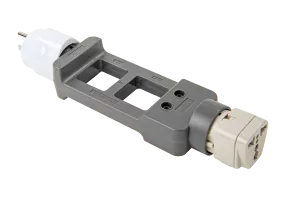
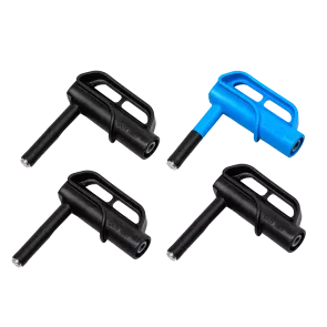
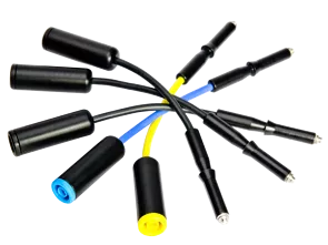
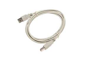
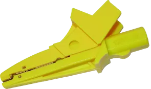
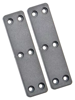
Accessories included with the meter